Thursday, December 11, 2014

12/12/14

As of today, the due date (12/12/14) the robot is not operational. The missing piece is the code which will
allow us to control the robot via Xbox controller. Other than that there is nothing holding the robot 
back from being fully operational. It's disappointing that we weren't able to finish the project on time 
but things like this happen and it doesn't mean we can't finish it after the fact.

Wiring

Here we have the Arduino mounted to the chassis directly under the seat, on top of the Arduino is the Adafruit motor shield with all four CIM motors plugged in. In addition to the motor wires, the positive and negative battery wires are also plugged into the motor shield so we get 12V power instead of 5V from the Arduino.


Sunday, November 30, 2014

Code and Wiring


We made this setup for simple variable speed of a 12V DC motor using a potentiometer. The accompanying code is below. Now we have to figure out how to configure this type of setup to work with four motors hooked up to a motor shield in such a way that the motors on same sides run together and have each side run independently ( two joysticks).


int potPin = A0;
int motorPin = 9;
int potValue = 0;
int motorValue = 0;
void setup() {
 Serial.begin(9600);
}
void loop() {
 potValue = analogRead(potPin);  
 motorValue = map(potValue, 0, 1023, 0, 255);
 analogWrite(motorPin, motorValue);  
 Serial.print("potentiometer = " );     
 Serial.print(potValue);
 Serial.print("\t motor = ");
 Serial.println(motorValue);
 delay(2);    
}

Saturday, November 29, 2014

Progress


The top half of a lightweight tubular aluminum chair has been fastened the the rear section of the chassis using several pieces of aluminum C-channel and secured tightly so it doesn't snap off and send someone flying. The chair is mounted very close to the chassis so that it keeps the center of gravity as low as possible for tipping reasons.


The dual battery setup was placed in the very center of the chassis, held in place by three L-brackets, one on each side and one behind the batteries that holds it tight against the chassis' crossbar. A cover was mounted over the battery with foam insulation to help protect the leads from getting damaged or somehow connected if something fell on them.


The positive lead of the batteries were connected to the 120A circuit breaker via a short piece of 6 gauge wire with the appropriate connectors crimped to each end.


We decided to create a small display panel that mounts to the front end of the chassis. It will contain an on/off toggle switch connected to the 9V battery running to the Arduino barrel connector so we don't have to remember to unplug it. We also utilized the small LCD screen that came in the Arduino starter kit; this will be used to display the instantaneous voltage of the 12V batteries. Along with the LCD screen we have 9 small LED's mounted across the top of the panel which will all be on at full battery life and at 10% increments shut off as the battery loses voltage.


Saturday, November 22, 2014

Progress

The chassis has been TIG welded and is one solid piece.
The chassis is surprisingly light for its size.


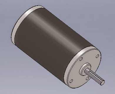
Both the left and right side drivetrains have been assembled and the chains/sprockets are set up to reduce the rpm values coming directly out of the 12V DC motors into a more practical and easier to control speed.


This is the basic set-up of the robot (just the drivetrain mounted to the chassis). Although the chassis was
very lightweight, the addition of the drivetrain makes the robot much heavier, almost too heavy to lift.


To power the robot we have taken two large 12V batteries and connected them via 6" bolts from lead to lead in parallel, then duct taped so they stay together indefinitely. This gives us twice the available amperage thus doubling our battery life. 

(Running these in parallel is important because if we ran them in series we would have doubled the 
voltage to 24V, which could result in the failure and destruction of several components of the robot.)


For safety and piece of mind we are going to run the power from the batteries to this 120A circuit breaker before it goes to the motor controller. This will allow us to simply push a button to kill the power to the system so we don't have to scramble to disconnect the battery leads if something bad starts happening.


We decided to power the Arduino board itself separately from the rest of the robot as a secondary security measure to make sure the robot doesn't start moving if the main 120A breaker is left on. We will have a 9V battery attached to the drum plug input connector on the Arduino with a simple toggle switch spliced into the positive wire.


Thursday, November 6, 2014

SolidWorks 3D Parts and Assemblies


Four of these CIM motors (12V DC)
will be used on our drivetrain.


Six of these 8x1.5 high 
friction wheels will be used.


Our chassis will be one solid piece of welded aluminum mainly consisting of 3/4" box aluminum extrusion and 2" angle aluminum, as well as an assortment of other aluminum pieces.


These four parts along with two motors will be used to construct a left and a right side drivetrain.


This is a rough estimate of what one side of the drivetrain will look like.
(not including driveshafts, sprockets and chains)


And finally here's a look at what the completed chassis/drivetrain will be.